
Lidar corridor

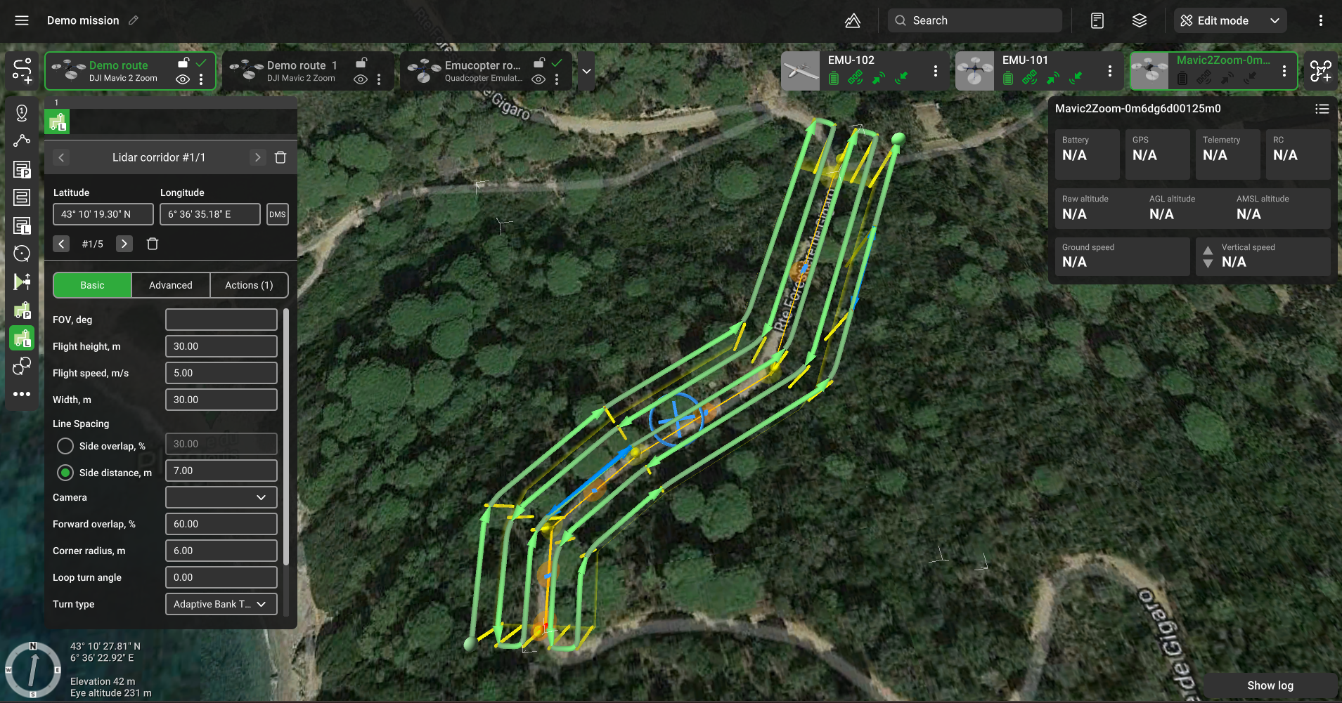
LiDAR corridor flight plan
The UgCS toolset for LIDAR mission planning is enabled for the UgCS EXPERT and ENTERPRISE licenses and supported DJI drones. To use the LIDAR toolset - create a new route for DJI M210/M200, M600, M300, M350, M400, or PX4/Ardu autopilots..
To get accurate LIDAR scan results, a pilot needs to follow the rules below:
• Initialise IMU properly
IMU initialization is typically performed at least two times per flight. Before scanning begins and after scanning ends. Optionally, the pilot may pause the flight and make additional IMU initialisation to reset accumulated errors. This function is implemented as a drone command, so the pilot may run it at any time. For this command to run, the drone should already be in the air.
• Maintain correct flight height and line spacing between scans to ensure coverage and point density
• Ensure the right drone turns and line scanning to minimise IMU error accumulation and excessive shaking of LIDAR above the area of interest.
LIDAR corridor scanning is helpful for the following: roads, power lines, and pipelines.
Basic

LiDAR - allows selecting the LiDAR profile and creating a new profile without the need to visit the main menu. If the payload profile is created using this option, it appears in the payload menu as a generic entry with one parameter only: Field of view.
- FOV, deg - field of view in degrees. It is the visible extent of the scene captured by the image sensor, stated as an angle. The default value is stored in the payload profile; however, it can be adjusted manually. The circular arrow near the input field resets the value to default.
- (DJI L-series sensors) - Return mode. Corresponds to the DJI native settings.
- (DJI L-series sensors) - Sampling rate. Corresponds to the DJI native settings.
- (DJI L-series sensors) - Scanning mode. Corresponds to the DJI native settings.
- (DJI L-series sensors) - Colorized point cloud. Corresponds to the DJI native settings.
Flight height - altitude of flight over the area.
Flight speed - speed of flight over the area.
Width - allows to specify the width of the pattern.
Line spacing - there are 2 options. A pilot can specify:
- Side overlap in per cent.
- Side distance.
In the case of a percentage, the software will calculate line spacing based on FOV and flight height.
Turn type - allows setting the turn type.
Altitude mode - Allows setting the altitude mode.
IMU Calibration - enables IMU calibration for a segment. More details here - LiDAR Calibration
Advanced

Forward overlap - the ratio of the overlap in neighbouring frames. Value is set in the range from 1% to 90%.
Corner radius - radius of adaptive turn.
Loop turn angle - the maximum value below which software will add loops for turns. For values greater than “Loop turn angle,” standard bank turns will be used. Range for the value: (0;180)
Default: 90.
AGL Tolerance - allows flying straight trajectories over the slightly waved landscape, by specifying how precisely the UAV should follow the required altitude above ground. To maintain a defined height, additional waypoints will be added if the height difference is larger than the AGL tolerance. The smaller the AGL tolerance value, the greater the number of waypoints that will be generated. If AGL tolerance is set to 0 (zero) UAV’s altitude will be constant throughout the route, but many additional waypoints will be added.
Straight flight after turn - for LIDARs, it is crucial to have at least X meters of straight flight after each turn before entering the next segment. Default: 10 meters.
Action execution:
- Every point – actions will be generated on all waypoints;
- At the start – the algorithm will generate actions only at the first waypoint.
Avoid obstacles – flag to be set if buildings have to be considered when planning the path. Do not uncheck without a specific need to do so.
Updated about 1 month ago