Fine-tuning axes via the GUI
Axis fine-tuning is performed via the interface. Click the “Input mapping” button, located at the top right corner. Checkbox the desired controller and select the axis that requires tuning.

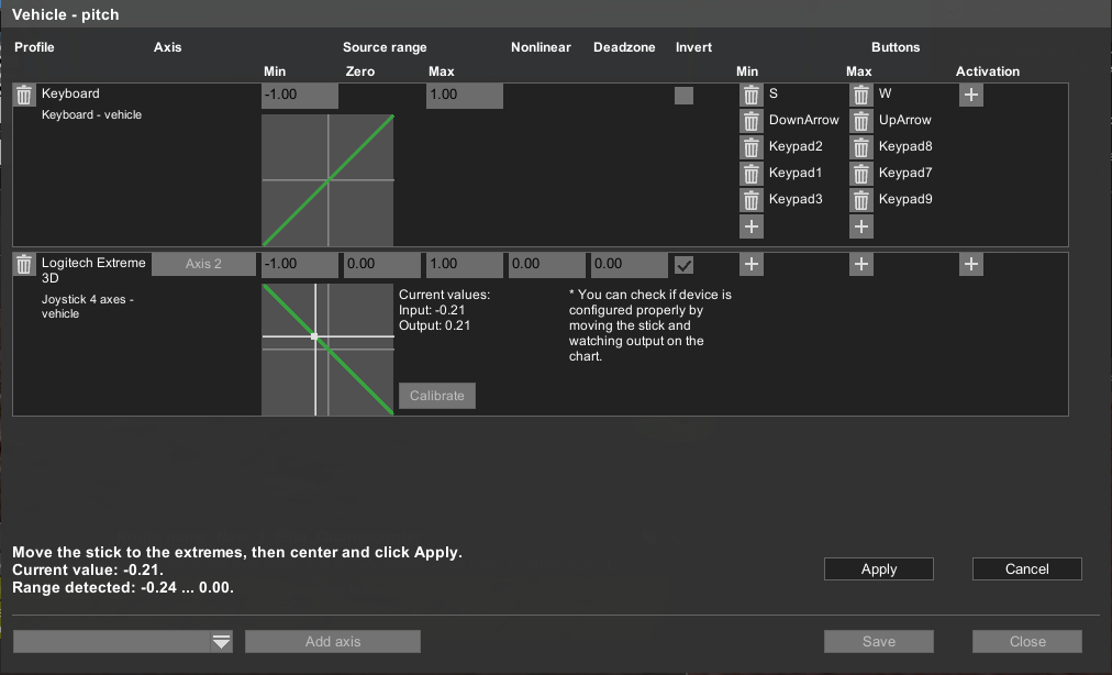
The window shows a list of the settings of the axis. Input and output axis of the profiles and devices. If the settings of axes more than fit the window to the right appears scroller.
The following actions can be performed:
• add configuration for the profile that does not yet have such an axis setting;
• add individual input button to configure axis;
• calibrate axis for the input device;
• delete added devices;
• configure boundaries and point zero, non-linearity, and "Deadband";
• check the results of device settings.
Add axis settings for a profile, which does not yet have such settings
In the “Input” window, select the function with no button (axis) assigned. For example. “Payload 1 – zoom” In the next module window, choose the controller of the dropdown menu located at the bottom left, and click “add axis”. Use the desired axis for the action on the controller. UgCS should detect it and notify the operator with the message “Currently detected: axis #” at the bottom. Click “Apply” and “Save”.
Adding a single input button to configure the axis
A single-action button is being set up the same way as an axis. Select the single action function – Drop down menu, select controller – add axis, and click “Cancel” instead of the axis editing window, will appear single action editing window. Click the “+” (plus) button, under the “activation” sign at the top, right corner of the modular window. Press the desired action button on the controller. UgCS will detect it and notify the operator with the message “Currently detected #” at the bottom. Click “Apply” and “Save”.
Calibration of input devices
Pressing the button "calibrate" (calibrate) enables the calibration mode. Movement along the axis of the device determines its minimum, maximum, and average values for the input. To accept or reject the changes will be prompted.
Remove individual buttons and axis
To remove the entire axis or a single action button, use the trash bin pictogram located at the modular calibration window. (click the required action to open it). The button is located at the beginning of the line, next to the device name and profile for the axis and at the end, for single-action buttons. Until “Save” is pressed, all changes remain unsaved, the window closes without saving.
Setting minimum, zero, peak, nonlinearity, the "dead zone"
These settings apply to the "input" signal from the control device in relation to the value of the main axis and are displayed as numbers with two decimal places. It’s possible to configure them manually. Minimum, zero, determine the maximum under what values on input, will -1, 0, and 1. Next, the output function is converted to a parameter with the nonlinearity of the curve, and adjusted around the "Deadband" to non-zero values started immediately behind the range (it is set to +-n around a given value of zero). Derived values are displayed at the bottom, in the form of graphics input to the output. A line chart displays both the function and the current i/o device on it. The side graphics these same data displayed in numeric form.
Note: Features work with the keyboard!
The keyboard has the following differences from other devices:
• Input axis search will not start when adding a keyboard;
• The current value is not displayed on the chart and calibration is not prompted.
• Input axis value zero, non-linearity, and dead zone are not displayed.
Updated 3 months ago
